Custom molded silicone components

Custom Silicone Diaphragms & Precision Valve Membranes

Application-led silicone diaphragms for valve, regulator and pump assemblies. Develop the membrane geometry, material, tooling and inspection plan around your actual pressure, stroke, sealing and service conditions.

Custom geometryTooling & prototypesMaterial selectionOEM enquiries
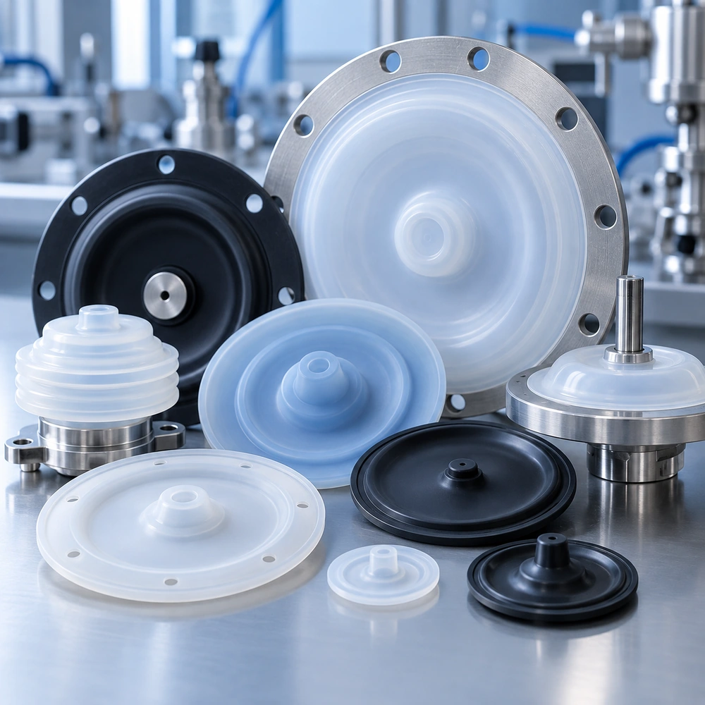
Silicone diaphragm component examples for custom manufacturing discussions
Reference diaphragm imagery — final part design is application-specific.
Diaphragm development

Design the membrane around how it moves and seals

A diaphragm separates chambers or transfers force while flexing under pressure. Its performance depends on more than silicone hardness: effective area, clamp geometry, wall transitions, expected displacement and media compatibility must work together.

For new OEM parts or replacement designs, our review starts with your drawings, duty cycle, sealing interface and acceptance criteria. Material and tooling choices are then evaluated against the assembly requirements.

  • ✓Geometry for controlled flex and defined clamping
  • ✓Silicone grade and reinforcement considered case by case
  • ✓Mold design informed by manufacturability and inspection

Core specification questions

Motion & load
Pressure differential, stroke or deflection, cycle rate and expected life.
Sealing interface
Flange width, clamp design, contact surfaces and allowable leakage.
Material environment
Operating temperature, fluids or gases and cleaning exposure.
Production brief
Drawing revision, sampling plan, target quantity and critical dimensions.
Geometry options

Custom molded diaphragm configurations

Common diaphragm forms require different tooling and validation decisions. The right configuration follows your stroke, differential pressure and mounting constraints—not a universal default.

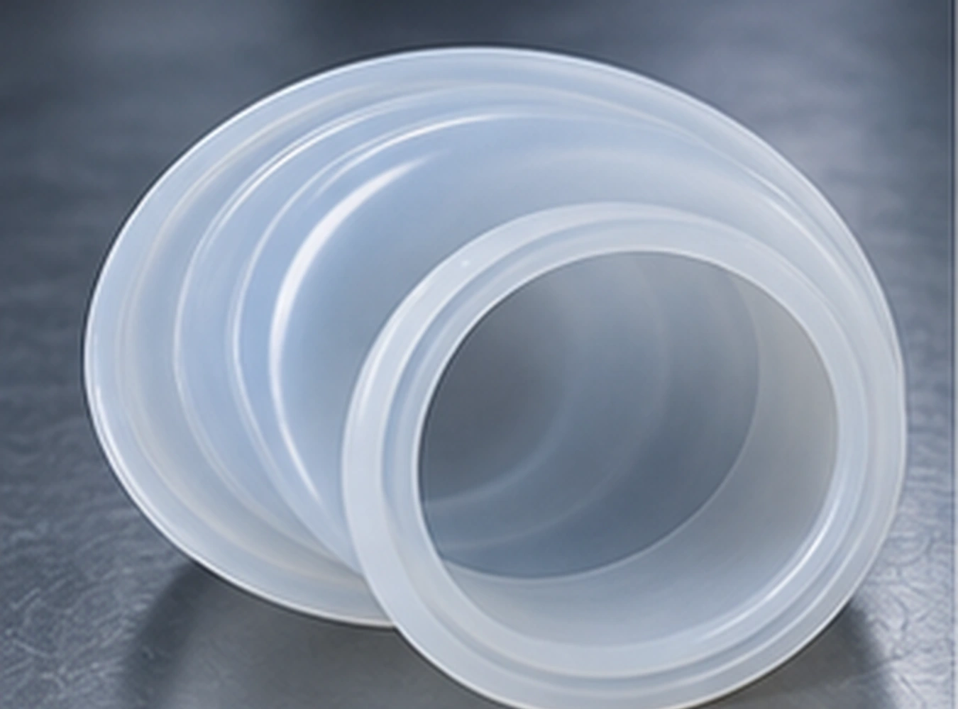
Rolling diaphragm silicone diaphragm reference illustration

Rolling diaphragm

For designs needing guided movement over a defined stroke; rolling profile and clearance require application review.

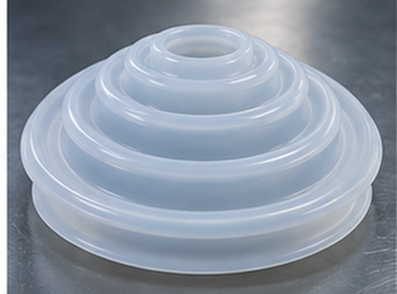
Convoluted diaphragm silicone diaphragm reference illustration

Convoluted diaphragm

Formed folds can support controlled travel when geometry, pressure and fatigue requirements are balanced.
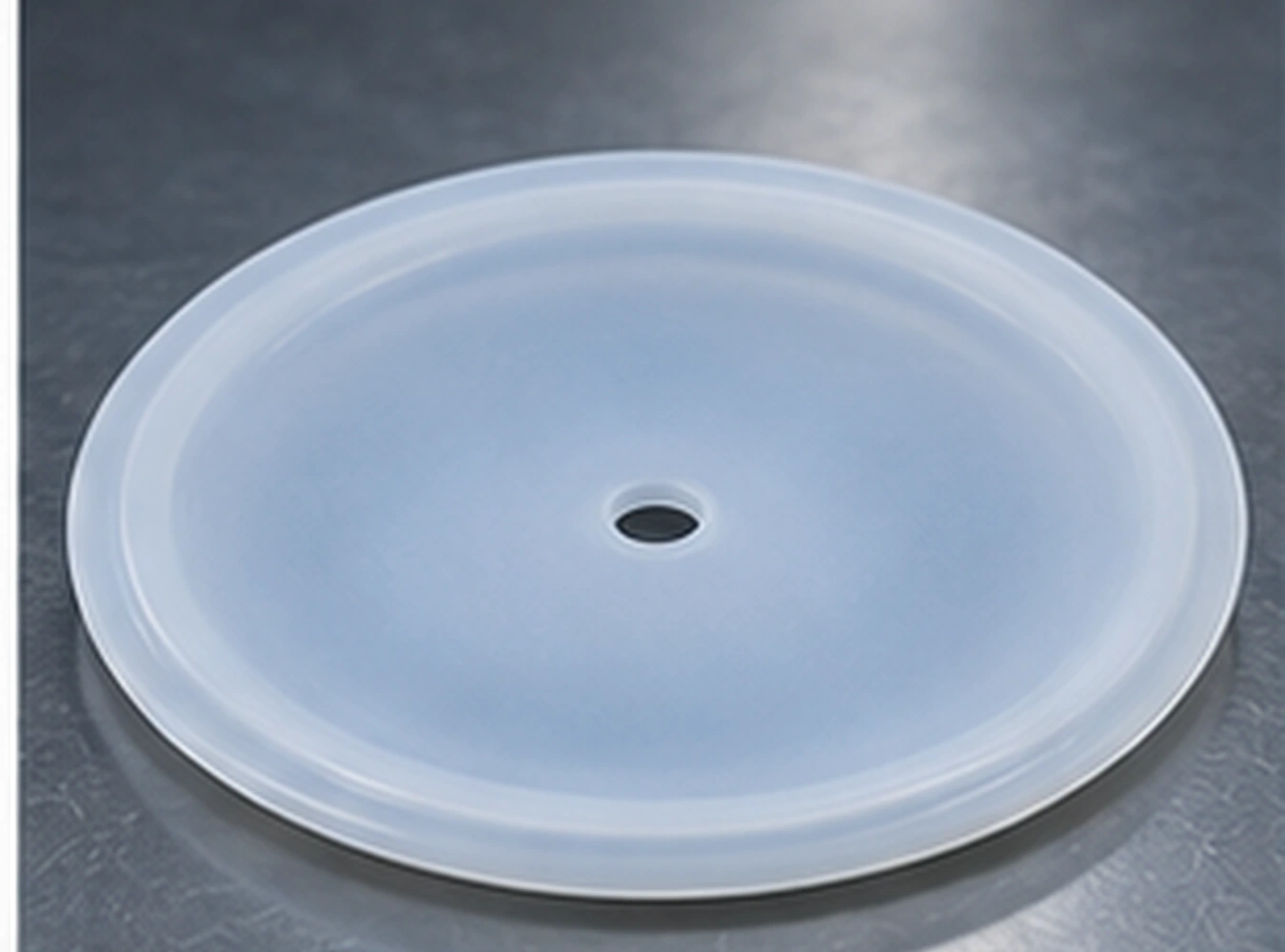
Flat disc membrane silicone diaphragm reference illustration

Flat disc membrane

A compact approach for clamped assemblies, subject to appropriate stress, deflection and seal design.
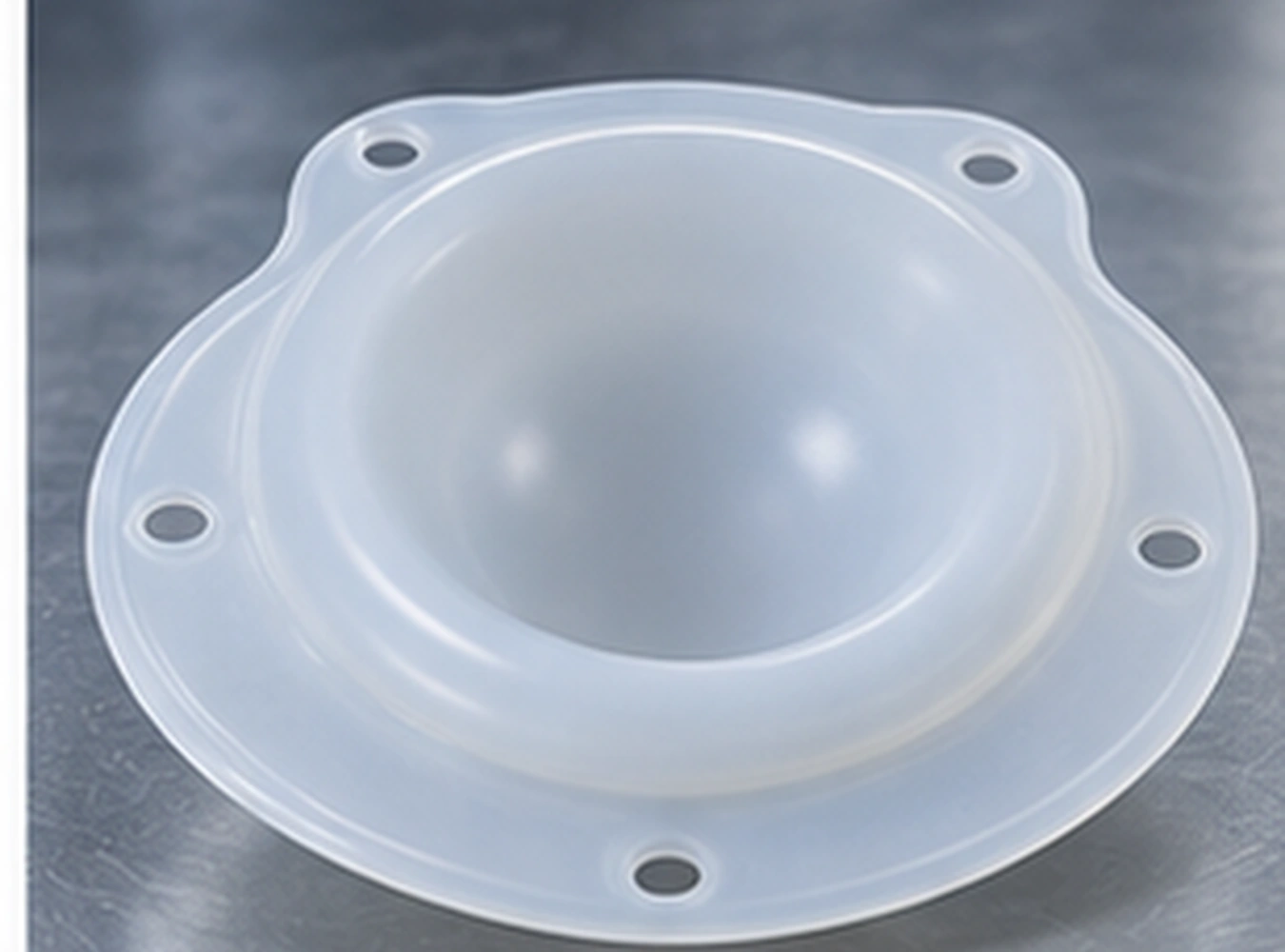
Dish-shaped diaphragm silicone diaphragm reference illustration

Dish-shaped diaphragm

Profiled geometry for assemblies where effective area and movement must be coordinated.

Material and construction

Choose construction to match the duty cycle

Flexibility, dimensional stability and attachment strategy must be considered together. The options below are design routes to assess, not guaranteed configurations for every project.

Silicone membrane application reference for valves and regulators

Homogeneous silicone

A flexible construction to evaluate where the required pressure resistance and movement can be achieved without added reinforcement.
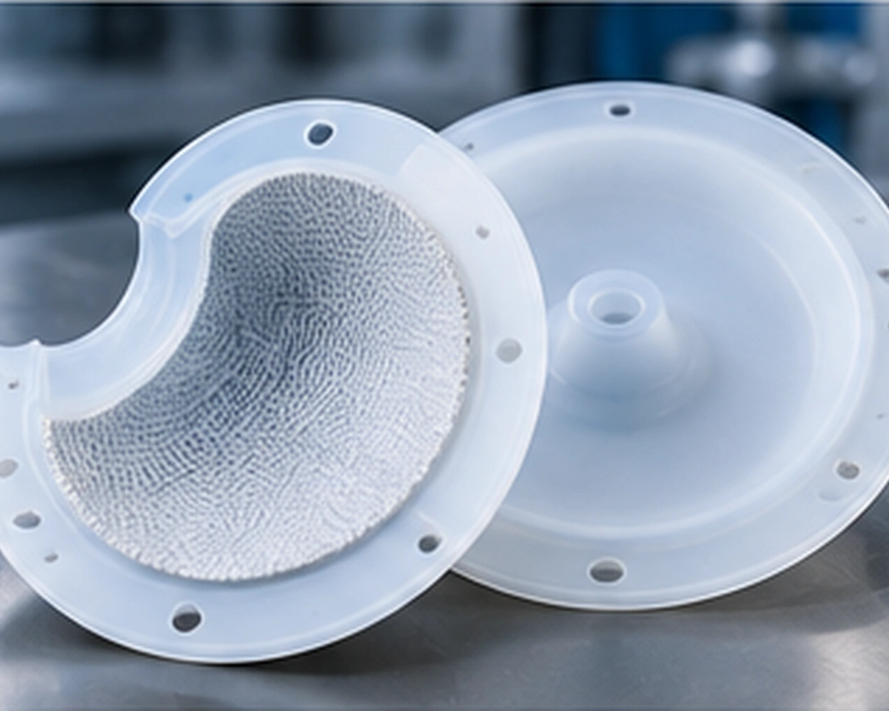
Fabric-reinforced silicone diaphragm construction reference

Fabric-reinforced options

Reinforcement may help manage stretching or dimensional changes. Fabric type, adhesion and flex life need validation for the application.
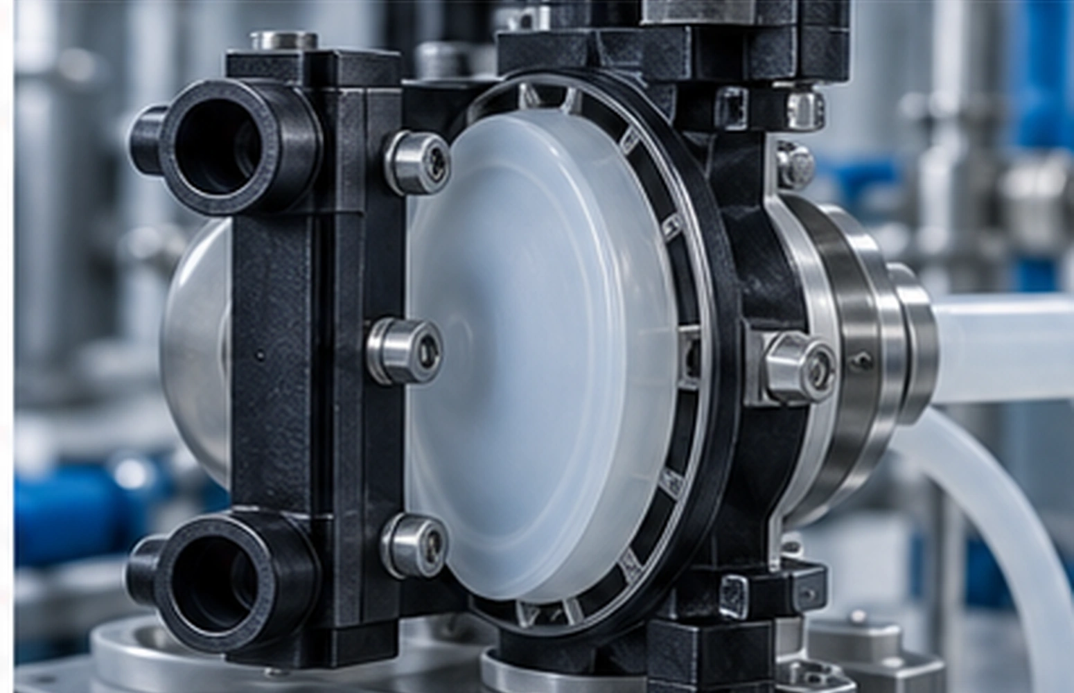
Silicone membrane used as part of a pump concept

Assembly and bonding review

Where inserts, rigid interfaces or bonded features are required, assess adhesion, fit and process feasibility during DFM.

Material caution: VMQ and other silicone formulations do not have one universal temperature, chemical-resistance or fatigue rating. Select the grade and test plan against actual exposure; suitability must be demonstrated for each application.

From CAD to molded part

A practical diaphragm manufacturing workflow

Define critical requirements early, then use prototypes and production tooling to establish a repeatable process.

01

Application & DFM

Review drawing, flange geometry, loading, stroke, material exposure and critical inspection dimensions.

02

Tooling concept

Plan parting lines, cavity details, flow, demolding and the areas affecting membrane thickness.

03

Process assessment

Evaluate compression molding or LSR processing according to material, geometry, volume and tool suitability.

04

Samples & inspection

Agree sample acceptance criteria and production controls before volume manufacturing.
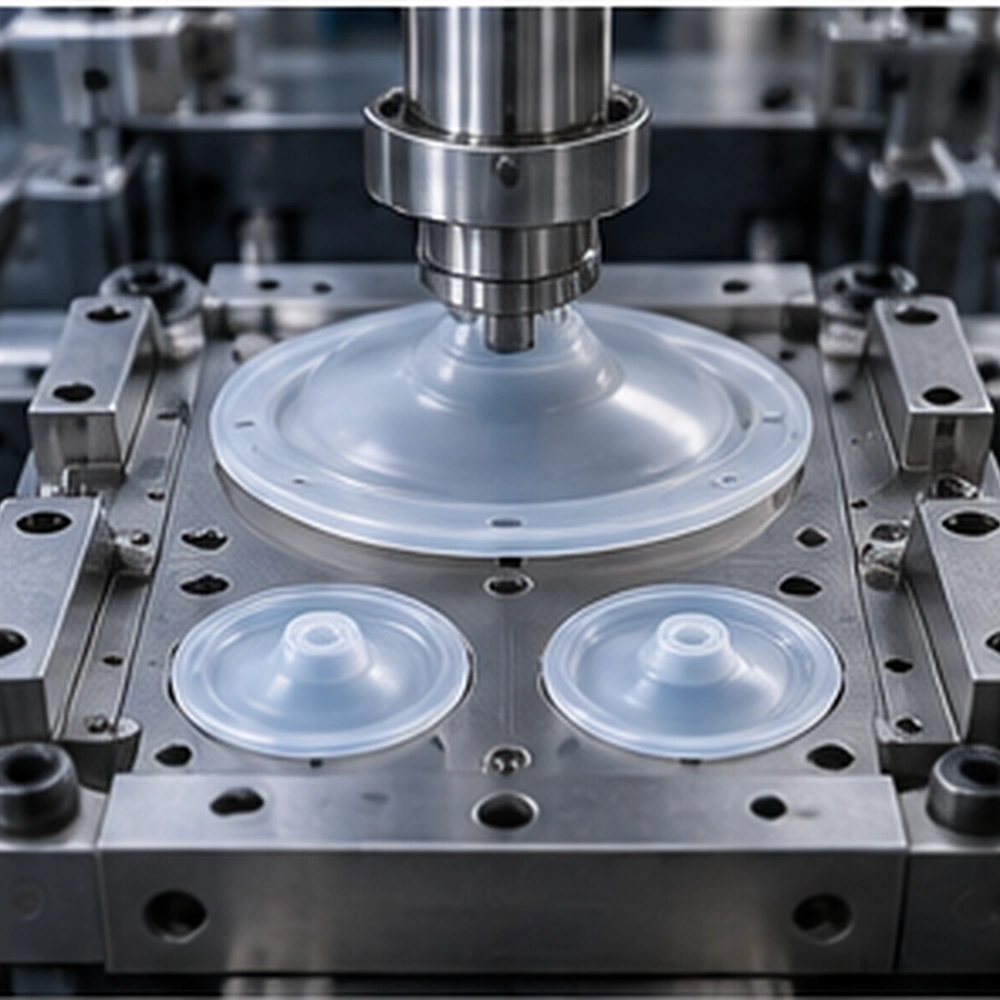
Molded silicone diaphragm manufacturing process reference

Tooling and production are linked

Thin areas, transitions, reinforcement positioning and mold venting influence part consistency. Engineering discussion should identify these risks before tool commitment.

Our silicone tooling capabilities and LSR injection molding service provide more context about related processes. Final route depends on your part.

Quality planning

Agree testing around the failure modes that matter

For dynamic sealing components, define acceptance criteria before production rather than assuming that visual inspection alone establishes performance.

  • Dimensional checks: thickness distribution, flange geometry, critical molded features and drawing revision.
  • Leak and pressure checks: evaluate the assembled seal under project-specific pressure and media conditions.
  • Repeated-motion assessment: discuss stroke, cycle count, fatigue and hysteresis requirements with the buyer.
  • Material consistency: review hardness, cure and relevant physical properties for the selected grade.

These are potential validation items. Availability, methods and pass/fail limits must be agreed for the specific project; no standard test result or lifetime is implied.
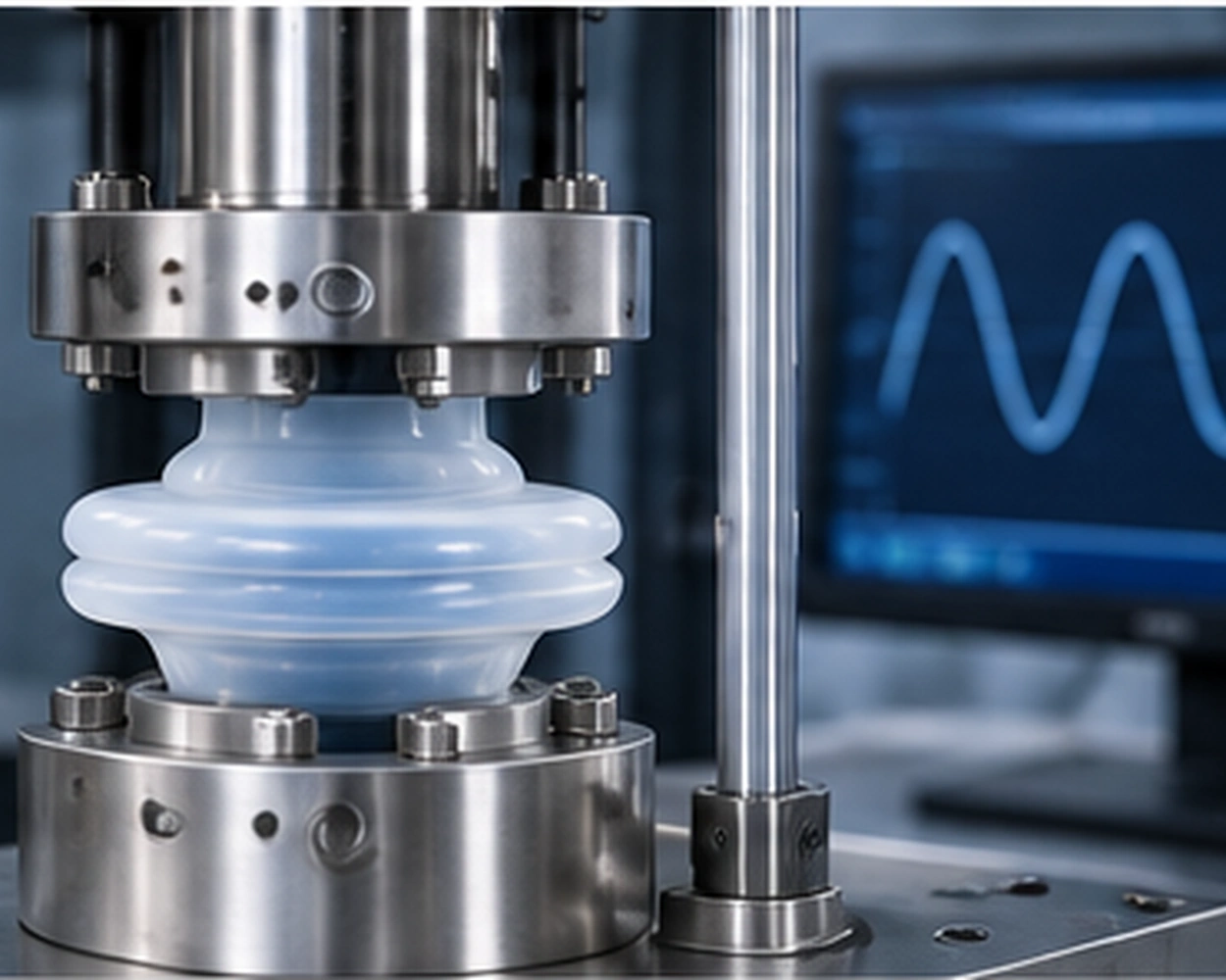
Silicone diaphragm fatigue and quality evaluation reference
Technical quotation

What to send for a useful diaphragm RFQ

The best starting point is a drawing or sample together with assembly conditions. If your design is at concept stage, share known constraints and flag open decisions.

  • 2D / 3D drawing or part sample
  • Overall diameter and membrane profile
  • Pressure differential and stroke
  • Operating temperature and process media
  • Expected cycles or service life
  • Silicone grade, hardness or reinforcement
  • Clamp and mating-part details
  • Prototype and annual order volume
FAQ

Custom silicone diaphragm questions

Practical considerations for material, process and assembly design.

What is the difference between a flat and a rolling diaphragm?

Flat membranes suit some clamped layouts, while rolling profiles can guide motion through a defined stroke. Selection depends on pressure, displacement, available space and seal geometry.

When should fabric reinforcement be considered?

Consider reinforcement when dimensional stability or stretch control is important under pressure or repeated motion. It can also affect flexibility, so the full assembly must be evaluated.

Can you review compression molding versus LSR?

Yes. The suitable process depends on material form, membrane thickness, geometry, tooling, production quantity and required repeatability. No single process is right for every diaphragm.

What temperature and chemical compatibility can be guaranteed?

There is no universal operating range for all silicone grades. Provide the fluid or gas, cleaning agents, temperature range and exposure time so appropriate material data and validation can be reviewed.

How do I begin a custom diaphragm project?

Share a drawing or sample, pressure and stroke conditions, sealing interface, material preference and anticipated production quantity. Use the contact form or email the CAD package to our team.

Ready to discuss a custom membrane?

Send your drawing and operating requirements for a project-specific discussion. For adjacent sealing components, browse custom silicone seals or the silicone parts service hub.

Request a Quote ↗