Rubber Mold Design & Tooling
Develop production-oriented rubber molds around part geometry, compound behavior and OEM output requirements. From early DFM and cavity planning to trial samples, focus tooling decisions on the parts you need to manufacture.
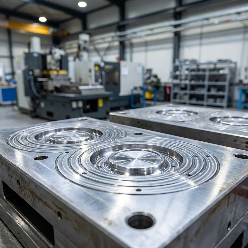
Tooling photograph from existing Temco service media; final design follows the approved project.
Real rubber mold tooling examples
Explore four documented tooling projects with different cavity, insert and functional-part requirements. Each project illustrates a specific scope; it does not imply identical tooling specifications for every order.
55-Cavity Rubber Mold
Published Temco rubber mold with a documented 55-cavity project title.
View published mold project ↗02 / INSERT COMPONENT TOOLRubber Mold with Two Internal Metal Inserts
A published rubber mold project involving two internal metal inserts.
View published mold project ↗03 / VALVE COMPONENT TOOLRubber Valve Disc Mold
Published mold example for a rubber valve-disc component.
View published mold project ↗04 / FUNCTIONAL PART TOOLRubber Stepper Motor Mold
A published rubber tooling project associated with a stepper-motor component.
View published mold project ↗Design the mold around the part and compound
A mold is a manufacturing system, not only a negative image of the finished part. Cure behavior, parting lines, venting, inserts, demolding and planned cavity count all affect the quality and repeatability of the molded rubber component.
Share CAD or a physical sample, material expectations, relevant assembly conditions and production estimates. These inputs frame a practical DFM discussion and reduce tooling rework risk.
Explore rubber mold manufacturing ↗Key mold-design inputs
- Finished-part definition
- 2D / 3D geometry, critical dimensions, fit and function.
- Rubber formulation
- Compound family, cure process, expected shrinkage and property targets.
- Production method
- Compression, transfer or injection requirements and available equipment.
- Output and acceptance
- Cavity target, volume, sampling and tolerance/inspection plan.
Four details that influence rubber mold performance
Tool design must control both the functional molded geometry and the practical steps used to produce and remove the part.
Parting line & flash
Position split surfaces and potential flash where they can be controlled and where function permits.
Venting & cavity fill
Assess air release, material flow paths and compound-specific behavior during filling and cure.
Shrinkage & release
Plan for material shrinkage, draft, demolding and removal of flexible or delicate features.
Production layout
Balance cavity count, tooling footprint, process and maintenance considerations against volume.
Rubber mold development workflow
A connected engineering and sample-validation process helps make tool design decisions visible before full manufacturing release.
Drawing & DFM review
Confirm target component, compound, production method and critical interface.
Mold design
Plan cavities, inserts, parting geometry, venting and necessary tool details.
Tool manufacture
Manufacture and inspect the tooling components against the approved design.
Trials & sample review
Review molded samples for fit, flash, release and specified critical dimensions.
Production handoff
Document required corrections and process considerations for repeat production.
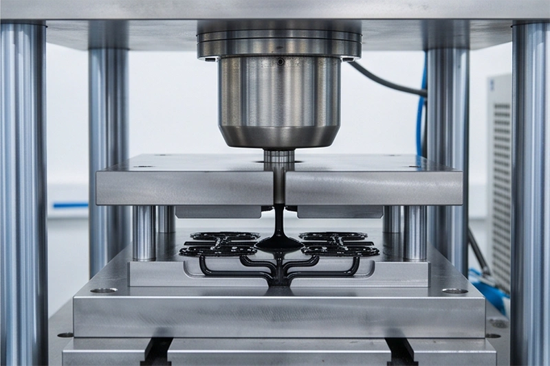
Machining details must support the selected rubber process
Final tools often rely on accurate cavity and alignment surfaces. Machine setup, finishing and tool checks should be considered alongside rubber compound and part geometry.
The material, steel grade, tool life and manufacturing lead time are not assumed to be identical across projects; these depend on the approved tooling scope.
Select the tooling approach for the production route
Rubber molding routes have different feed and cure considerations. Process selection should be based on the actual compound, part geometry and production goals.
Compression mold tooling
Review charge placement, pressure, cure behavior and demolding for the selected rubber compound.
Transfer mold tooling
Assess runner flow, transfer paths, cavity fill and compound-specific restrictions.
Rubber injection mold tooling
Evaluate feed, runner and injection conditions where equipment, geometry and production volume justify the process.
Process and tooling caution: no universal mold tolerance, cavity count, steel specification, cycle time or lifetime is guaranteed. Confirm requirements during quotation and tool approval.
Inserts, multiple cavities and functional mold features
Real Temco portfolio projects include multi-cavity tooling and a mold with internal metal inserts. For new projects, these features need their own handling and validation requirements.
Metal insert positioning
Review insert location, retention, rubber-to-metal interface, placement and release requirements. Insert handling changes the tooling and production plan.
View insert mold project ↗Cavity count & consistency
More cavities affect tool fill, balancing, sampling, production handling and maintenance. Evaluate these together with expected volume and part dimensions.
View 55-cavity mold project ↗Verify the tool through the samples it produces
A useful tooling approval evaluates molded-part features and production practicality against agreed criteria, not only whether cavities are machined to shape.
Tool and part geometry
- Parting lines, mold alignment and cavity geometry
- Key molded dimensions, profile and surface appearance
- Flash-sensitive and undercut features
- Insert locations or critical fit points where applicable
Production and validation
- Demolding, release and part handling
- Sample fit and other buyer-defined functional checks
- Process changes identified from first trials
- Tool maintenance and inspection needs
Verification methods, measuring equipment, sample quantity and specific acceptance limits should be agreed for each project before tooling release.
What to send for a rubber mold quotation
Provide your CAD model or existing part sample, plus the relevant molding compound and production conditions. Clarify which dimensions or features must be validated at first samples.
- 2D / 3D CAD and drawing revision
- Physical part sample if available
- Rubber compound and cure needs
- Compression / transfer / injection route
- Key dimensions and tolerances
- Inserts, undercuts or special features
- Target cavities and annual volume
- Sample, inspection and delivery goals
Connect mold engineering with the manufacturing program
Rubber tooling is part of a wider part-development process. Explore adjacent services based on the actual material and target product.
Rubber Mold Manufacturing
Detailed overview of mold manufacturing for rubber components.
Explore service ↗Rubber Parts Manufacturing
Adjacent molded rubber part services for OEM programs.
Explore service ↗Silicone Mold Design & Tooling
Tooling considerations when a silicone formulation and process are involved.
Explore service ↗Rubber mold design and tooling questions
Practical decisions to clarify during early development and tooling quotation.
What information is needed for a rubber mold quotation?+
Provide CAD or a physical sample, rubber compound requirements, critical features and dimensions, expected production volume and the intended molding route.
Can a new mold be developed from an existing part?+
An existing part can provide useful geometry, but shrinkage, mating interfaces, critical dimensions and the production process should still be confirmed before tool design.
How do you decide between compression, transfer and injection molds?+
The appropriate approach depends on compound, part geometry, equipment, volume, process constraints and tooling economics. It is evaluated case by case.
Can a rubber mold incorporate metal inserts?+
Some projects can use inserted components. The positioning, rubber-to-metal interface, retention and demolding requirements need a specific feasibility review.
How many cavities should the mold have?+
Cavity count depends on output targets, part size, machine compatibility, mold balancing and quality needs. A published 55-cavity project does not define the right cavity count for every part.
How are flash and parting lines considered?+
Their location and control are reviewed during DFM together with vents, cavity geometry, tool alignment and finishing requirements.
What should be inspected during first tool trials?+
Typical review points include critical molded dimensions, surface finish, flash, release, fit, insert position and any buyer-defined functional requirements.
Can you handle a production-focused mold redesign?+
Share the existing drawings, sample results, known defects, required changes and planned volumes. A revision can then be scoped and evaluated.
Have a rubber part that needs tooling?
Share a drawing, sample or production challenge to begin a DFM and mold-design discussion. See more rubber mold projects.
