OEM elastomeric keypad development

Silicone Keypad Tooling & Prototyping

Develop silicone keypads around the enclosure and PCB, not only the visible key shape. Review the key web geometry, actuation force, travel, conductive contacts and surface graphics before committing to tooling and production.
Keypad DFMTactile targetsPCB contact alignmentPrototype review
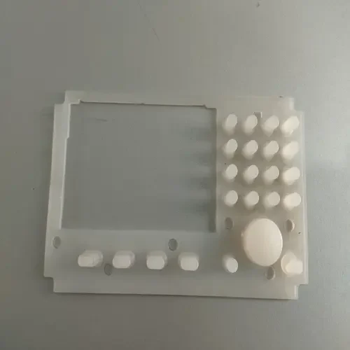
Published silicone keypad reference imagery for custom keypad development
Existing Temco keypad image. Geometry and manufacturing route depend on each project.
Interfaces first

Start from PCB contacts, housing and key function

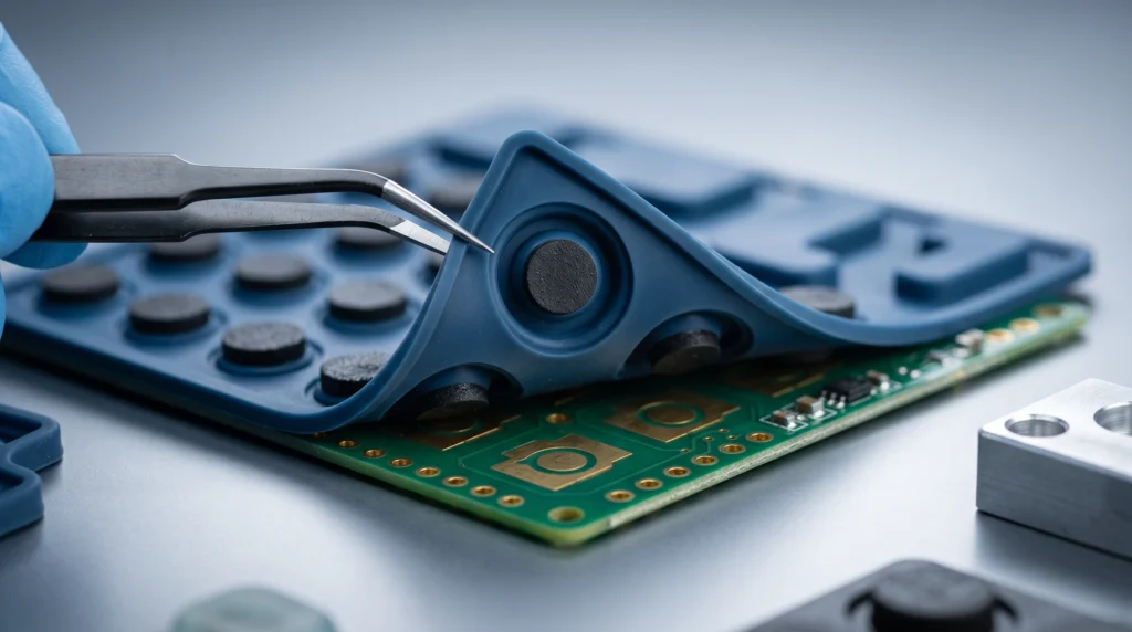
Keypad tools must integrate the elastomeric key profile with the housing and circuit board. Dome and web geometry influence tactile response, while carbon-contact position and PCB pad details influence switching.

Bring together the electronics, product-design and tooling inputs early. A physical sample, CAD model or PCB drawing can help define the critical dimensions before first trials.

Explore silicone keypad manufacturing ↗

Four groups of design inputs

PCB and electrical layout
Contact-pad locations, tolerances, switch type, alignment and possible conductivity needs.
Tactile targets
Key travel, desired operating force, snap response and expected use cycle.
Mechanical integration
Housing geometry, key spacing, constraints, fastening and installation clearances.
Legends and appearance
Text, colour, printing, translucency, lighting and wear or coating requirements.
Geometry and tooling

Critical details in silicone keypad mold design

DFM decisions should support the user-interface requirements and create features that can be molded, released and inspected.

01

Web and dome geometry

Geometry and thickness influence travel, force and the shape of the tactile response.

02

Key spacing and guides

Key centre positions, housing clearance and alignment affect feel and repeatability.

03

Conductive contact design

Define carbon-pill or other contact locations against PCB pad geometry and switching criteria.

04

Tool parting and release

Consider flash, vents, demolding and where features will be measured or finished.

Human interface

Plan tactile behaviour before production tooling

Force-displacement response is a result of the silicone formulation, web geometry, keycap form and assembly conditions. Prototypes should be evaluated with the intended housing and PCB.

01 / TACTILE PLANNING

Force and travel targets

Define acceptable actuation force, stroke and repeatability using a buyer-approved measurement plan.

02 / TACTILE PLANNING

Tactile response and snap

Discuss desired tactile feel and suitable web geometry, without assuming a universal snap-ratio target.

03 / TACTILE PLANNING

Prototype iteration

Evaluate samples in the real device assembly, record issues and agree the next tooling revision.

Measurement note: No universal travel, actuation force, snap ratio or cycle life is guaranteed for all silicone keypads. Define the test fixture, target values and acceptance limits per design.

Development workflow

From keypad drawing to approved prototype

Coordinate the tooling plan with PCB and housing revisions, so critical changes are identified before repeat manufacturing.

01

Keypad and PCB DFM

Review drawings, key profiles, housing interfaces and switching locations.

02

Mold concept

Plan cavity geometry, parting, venting, demolding and sampling access.

03

Prototype molding

Produce project-specific samples for tactile, dimensional and contact review.

04

Test and revise

Compare sample response against defined electrical, mechanical and appearance needs.

05

Production handoff

Agree final tool revision and a suitable production/inspection plan.

Carbon conductive contacts on the underside of a silicone keypad
Electrical contact design

Evaluate conductive contact position and switching

Conductive carbon-pill geometry is one possible contact approach. The correct contact material, position and switching behaviour depend on the PCB layout, application and specified acceptance method.

  • ✓Align contact features to PCB pads and reference datums
  • ✓Review compressed contact travel and mechanical interference
  • ✓Specify switch-function and electrical acceptance criteria
  • ✓Agree prototype contact measurements before tooling approval
Prototype acceptance

Inspect the complete keypad interface

Define the acceptance plan early. The functional keypad is more than the molded rubber component: fit, tactile response, contact and appearance must work together.

Mechanical and tactile checks

  • Key centre positions, height, wall and web geometry
  • Assembly fit within the actual enclosure
  • Key travel and force-displacement behaviour
  • Parting-line, flash and visible surface quality

Electrical and finishing checks

  • Carbon-pill alignment and switching response, when used
  • PCB contact behaviour under defined test conditions
  • Printed or laser-marked legend position and appearance
  • Backlight, colour and coating requirements where specified

These are proposed review items, not claims of specific test machines, regulatory certifications, achieved cycle counts or default tolerances. Agree scope before the first trial.

Technical quotation

What to include in a keypad tooling RFQ

Send a drawing or sample with the PCB and assembly references. Identify performance and appearance targets separately from features that are still being designed.

  • 2D / 3D keypad drawing or sample
  • PCB layout and contact datums
  • Housing geometry and key spacing
  • Target actuation force and travel
  • Carbon contact or other switching approach
  • Colour, printing and backlight brief
  • Prototype and acceptance tests
  • Annual volume and project schedule
Buyer FAQ

Silicone keypad tooling questions

Practical considerations when developing a new elastomeric switch interface.

What should I send for a silicone keypad tooling quote?

Send PCB layout, keypad drawing or sample, enclosure references, target key feel, contact details, cosmetic requirements, prototypes needed and production volume.

Can silicone keypad tooling be designed from a sample?

A sample can help define geometry, but PCB alignment, assembly tolerances, silicone properties and intended actuation requirements should also be confirmed.

What determines key travel and actuation force?

Web shape, key geometry, material formulation, thickness and surrounding assembly affect the force-displacement response. Prototype measurements should be evaluated against your stated targets.

Can keypads use conductive carbon contacts?

Carbon pills can be considered for suitable contact designs. Exact location, material and contact behaviour must be evaluated with the PCB and required switching tests.

Can keypads have printed legends or backlighting?

They can be considered at the design stage. Geometry, colour, printing, laser marking, coatings and translucent areas must be assessed for the intended production route.

How do you review first keypad samples?

Review mechanical fit, key alignment, travel and force, contact switching, flash and surface condition as well as relevant legends and appearance requirements.

Can the mold be revised if the feel is wrong?

Prototype findings can guide a tooling revision, subject to feasibility, tool-change scope, cost and a new approval plan.

What is the best molding process for a custom keypad?

Evaluate the silicone formulation, web geometry, tooling, production quantity and surface-finish requirements. No single process is correct for every keypad.

Ready to review a silicone keypad project?

Share your keypad drawings, PCB layout, target tactile response and application requirements for an engineering and tooling discussion.

Request a Keypad Tooling Quote ↗