Custom mold engineering for silicone components

Silicone Mold Design & Tooling

Develop molds for custom silicone components around the actual part geometry, selected material system and production process. From CAD and DFM review through tooling, samples and production handoff, focus each engineering decision on your OEM component.
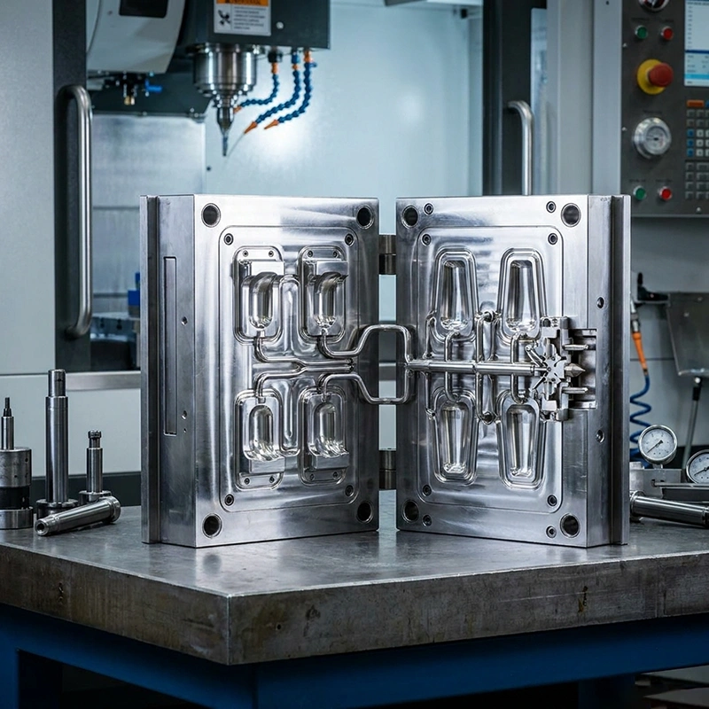
Design for manufacturingCompression / LSR reviewCustom cavitiesSample approval
Silicone mold and tooling manufacturing reference image
Existing Temco tooling imagery. Final mold configuration is specific to the project.
Engineering inputs

Design the mold around silicone behavior

Silicone tooling involves more than translating a CAD solid into a cavity. Wall thickness, flow, venting, cure behavior, parting lines and demolding influence the finished part, tooling practicality and sampling results.

Both solid silicone and liquid silicone rubber may be relevant, but they have different process and tool-design requirements. Start with the application and material system before choosing the mold route.

Explore custom silicone parts manufacturing ↗

Define these before designing steel

Part drawing & assembly
2D/3D geometry, interfaces, sensitive features and drawing revision.
Material and cure
Silicone type, hardness expectations, shrinkage assumptions and cure needs.
Process route
Compression, transfer or LSR injection feasibility and machinery interface.
Production objectives
Cavity expectations, annual volume, samples and acceptance criteria.
Design for manufacturability

Where silicone mold design decisions matter most

A mold concept should anticipate how silicone enters, cures and releases from the cavity while preserving intended function.

01

Thin walls and transitions

Consider cavity filling, local deformation, part thickness and demolding challenges.

02

Flash-sensitive features

Place parting lines and vents around functional and cosmetic requirements.

03

Release and undercuts

Evaluate flexibility, draft, ejector or manual release for delicate features.

04

Cavity and cycle planning

Review cavity count, process capacity, part size and overall tooling economics.

Development workflow

From silicone-part CAD to mold approval

Connect DFM, tooling, samples and production review to make tool corrections manageable and project decisions traceable.

01

CAD and DFM review

Identify geometry, silicone system, assembly requirements and critical dimensions.

02

Mold concept design

Review cavities, split surfaces, vents, flow or runner needs and release details.

03

Tool manufacture

Build and assemble mold elements in line with the approved engineering package.

04

Trial samples

Assess part appearance, fit, dimensions, cure or function against agreed criteria.

05

Production handoff

Resolve open tool and processing issues before planned repeat production.
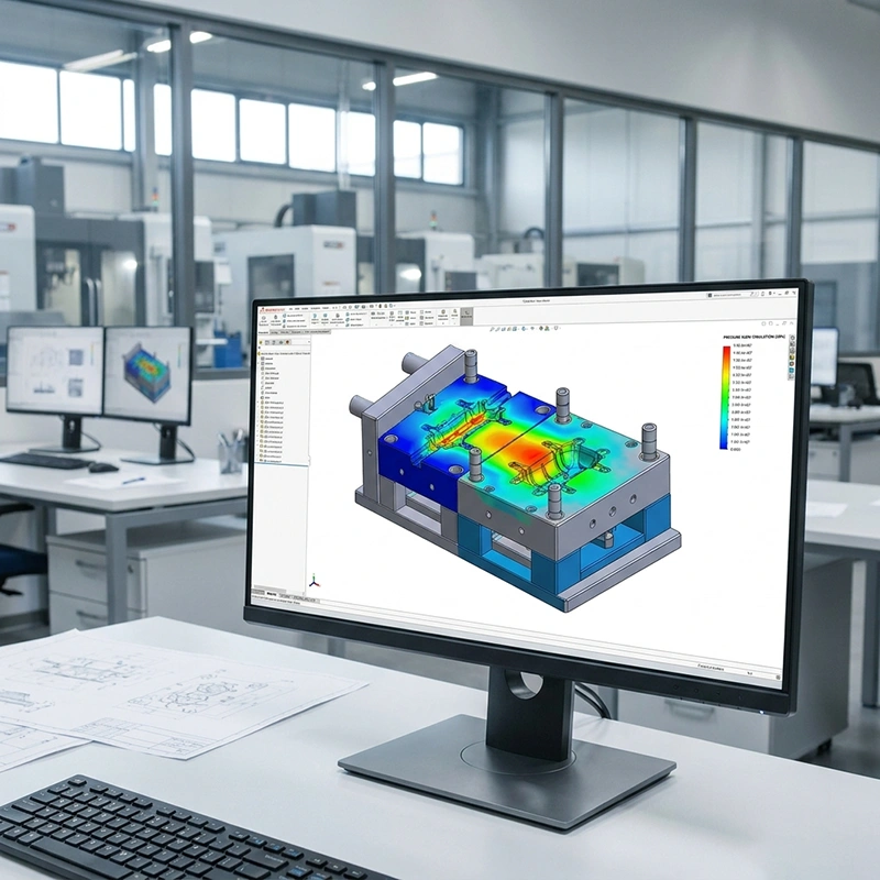
Silicone mold CAD design engineering reference

CAD details have manufacturing consequences

Small ribs, gates, undercuts and transitions can drive mold complexity and processing decisions. Reviewing them before tool commitment can avoid preventable revisions.

The exact tooling material, machining method, lead time and validation equipment depend on the agreed scope; no fixed numerical guarantee is implied.

Choose the right molding system

Compression, transfer or LSR injection tooling?

These methods are not interchangeable. The silicone grade, part complexity, tool design and production economics should guide the choice.

01 / PROCESS ROUTE

Solid silicone compression tooling

Review charge placement, compression, cure, release and compound-dependent mold features.

02 / PROCESS ROUTE

Silicone transfer mold tooling

Evaluate transfer paths, flow into the cavity and relevant material/process constraints.

03 / PROCESS ROUTE

Liquid silicone rubber (LSR) tooling

Assess injection feed, gating, venting, tool thermal behavior and suitable production equipment.

Qualification note: No single mold guarantees a specified tolerance, cycle time, production rate or certification across all silicone grades and part geometries. Agree technical targets during quotation and mold approval.

Application-specific mold features

Develop the tooling details around functional risk

Project requirements such as integrated sealing features, tool alignment or thin membranes often need dedicated manufacturing decisions.

Complex profiles and sealing surfaces

Review molded sealing edges, ribs and contact geometry with particular attention to flash, fill and dimensional inspection.

See silicone sealing tool project ↗

Shape fidelity and demolding

When parts include undercuts, grooves or flexible profiles, evaluate how they are removed and how tool surfaces can be accessed and maintained.

See silicone pad mold project ↗
Samples and inspection

Use mold trials to verify the molded silicone part

Tool evaluation should consider both the part's functional details and the stability of the chosen manufacturing method.

Part and tool geometry

  • Critical molded dimensions and drawing revision
  • Flash-sensitive faces, parting lines and vent marks
  • Surface appearance and feature definition
  • Alignment, insert or core details where relevant

Process and part release

  • Demolding and geometry-sensitive handling
  • Cure or post-cure criteria for the selected material
  • Sample fit, sealing or buyer-defined function
  • Corrective actions before repeat production

The actual measurement systems, test plan, frequencies and acceptance ranges are defined by the project. These items are possible review criteria, not universal promises.

Project quotation

What to include in a silicone mold RFQ

Share the design or sample and your intended silicone grade or application conditions. Clarify what is fixed and where engineering development is still required.

  • 2D / 3D CAD or part sample
  • Silicone grade, cure or material brief
  • Critical dimensions and interfaces
  • Compression / transfer / LSR preference
  • Undercuts, inserts or fine features
  • Target volume and cavity expectations
  • Required samples and tests
  • Drawing revision and project timing
Technical FAQ

Silicone mold design and tooling questions

Common engineering decisions for evaluating a new silicone mold project.

What should be included in a silicone mold quotation?

Share CAD or a physical sample, silicone type and expected hardness, key part dimensions, intended production process, volume and acceptance criteria.

Can a mold be designed from a silicone part sample?

A sample can help define part shape, but fit, shrinkage, material type and critical dimensions still need confirmation before designing production tooling.

What is the difference between compression and LSR mold tooling?

Compression tooling is designed for solid silicone charges and cure in the mold, while LSR tooling supports metered liquid injection and grade-specific temperature and flow control.

How are parting lines and flash controlled?

They are considered together with component geometry, tool fit, venting and processing needs. Sensitive sealing and cosmetic surfaces should be identified in the drawing.

Do you make molds for silicone seals and gaskets?

The service covers tooling discussions for custom silicone parts including seals and molded profiles. Project geometry and processing feasibility determine the exact mold approach.

How many mold cavities do we need?

Cavity quantity depends on part size, production volume, chosen material/process, balancing, tooling economics and handling requirements.

What is reviewed during silicone tool trials?

Samples can be checked for critical geometry, appearance, release, flash and any project-specific functional requirements agreed with the buyer.

Can the design be updated after the first samples?

Sample feedback can inform revisions. The tool design, change scope, cost and timing should be reviewed before committing to modifications.

Ready to discuss a custom silicone mold?

Send your drawing or existing sample and the silicone part requirements for an initial DFM and tooling review.

Request a Silicone Mold Quote ↗